
ESP32 With ASD1015/1115 I2C External ADC Using Arduino IDE.
The ESP32 development board is one of the go-to options when it's comes to embedded system and IoT prototyping, mainly because of it's relatively small form factor and inbuilt Bluetooth and Wi-Fi. But, you'll always have a second thought about the ESP32 board when trying to interface and read analog signal from devices connected to the board.
Although, ESP32 has two built-in ADC modules namely; ADC0 and ADC1 and
each channel is of 12-bits. But, the main issue with these inbuilt ADC modules is that it has a non-linear behavior. It can not differentiate between 1mv and 2mv signals which means it offers very low resolution.
Although we can use voltage divider to try and tackle this issues, it's not always reliable and sometimes does not even work at all. We can also use external high resolution programmable ADC IC such as ADS1115/1015, which is what we will be using here. So, we will interface the ADS1115/1015 to ESP32 through I2C then interface our analog sensors to the external ADC.
ADS1115/1015 External ADC
For microcontrollers without an analog-to-digital converter, or when you want
a higher-precision ADC, or the inbuilt converter has irregularities like in this case with the ESP32, the ADS1115 / ADS1015 is somewhat the popular options.
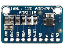
ADS1115 ADC
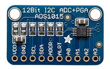
ADS1015 ADC
The ADS1115 and ADS1015 4-channel breakout boards are perfect for adding high-resolution analog-to-digital conversion to any microprocessor-based project. These boards can run with power and logic signals between 2v to 5v, so they can be compatible with all common 3.3v and 5v processors. As many as four boards can be controlled from the same 2-wire I2C bus, giving you up to 16 single-ended or 8 differential channels. A programmable gain amplifier provides up to x16 gain for small signals.
These two boards are very similar, meaning they are connected the same way and even function with the same library. They differ only in resolution and speed. The ADS1115 has higher resolution and the ADS1015 has a higher sample rate.
ADS1115 Features:
-
Resolution: 16 Bits.
-
Programmable Sample Rate: 8 to 860 Samples/Second.
-
Power Supply/Logic Levels: 2.0V to 5.5V
-
Low Current Consumption: Continuous Mode: Only 150uA Single-Shot Mode: Auto Shut-Down.
-
Internal Low-Drift Voltage Reference.
-
Internal Oscillator.
-
Internal PGA: up tp x16.
-
I2C Interface: 4-Pin-Selectable Addresses.
-
Four Single-Ended or 2 Differential Inputs.
-
Programmable Comparator.
ADS1015 Features:
-
Resolution: 12 Bits.
-
Programmable Sample Rate: 128 to 3300 Samples/Second.
-
Power Supply/Logic Levels: 2.0V to 5.5V
-
Low Current Consumption: Continuous Mode: Only 150uA Single-Shot Mode: Auto Shut-Down.
-
Internal Low-Drift Voltage Reference.
-
Internal Oscillator.
-
Internal PGA: up tp x16.
-
I2C Interface: 4-Pin-Selectable Addresses.
-
Four Single-Ended or 2 Differential Inputs.
-
Programmable Comparator.
You can also make use of this two-in-one ADS1015/ADS1115 module then edit your code to select which resolution you wish to make use of.

Pinout
Addressing modes can be set in four different mode by connecting address pin with SCL, SDA, GND, or VDD. The table below provides description on connection of address pin with SCL, SDA, GND or VDD pin according to value of address.
ADDR pin is used for selection of four different devices with one pin. So, we can connect it with any of four pins listed in table.
Testing
Hardware needed:
-
ESP32 board
-
ADS1015 ADC
-
Breadboard
-
Male-Male Jumper wires
-
Potentiometer
Circuit

Programming with Arduino IDE
If you're new to the ESP32, you can follow our tutorial here.
Installing the ADS1115 library in Arduino IDE
-
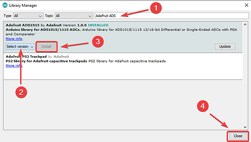
Open Arduino IDE, follow this menu: Sketch > Include Libraries > Manage libraries.

-
A window should pop up. Type Adafruit in the search bar and related options should pop-up. Select Adafruit ADS1X15 and select version 1.0.0 if you're using the code in this tutorial.
-
After installing the library, close the Library Manager window and restart Arduino IDE, as shown below:
Arduino Code
We'll use the code below to read analog readings from a potentiometer and display on Serial monitor:
#include <Wire.h>
#include <Adafruit_ADS1015.h>
Adafruit_ADS1015 ads(0x48);
float value = 0.0;
void setup(void) {
Serial.begin(9600);
ads.begin();
}
void loop(void){
int16_t adc0;
adc0 = ads.readADC_SingleEnded(0);
Serial.print("AIN0: ");
Serial.print(adc0);
Serial.println("");
delay(100);
}
Code working
The first two lines are used to add the "Wire.h" for I2C and "Adafruit_ADS1015.h" for our ADC module. You can edit the Adafruit library to ADS1115 depending on the module you're using.
#include <Wire.h>
#include <Adafruit_ADS1015.h>
After importing our libraries, we'll then define the sensor type and address mode
(we're using the ADS1015 here). Next we'll declare a variable of type "float" to store our analog potentiometer values.
Adafruit_ADS1015 ads(0x48);
float value = 0.0;
Next, in the "void setup" we'll initialize the Serial monitor and then initialize the ADS to begin reading values.
void setup(void)
{
Serial.begin(9600);
ads.begin();
}
Lastly, in the void loop, we'll specify the channel we're reading our analog input
from (A0 in this case). Then we'll print the results.
You can check the Adafruit website for more information on how to use this library.