
Digital Inputs and Outputs:
LED/Push Button
Updated: Feb. 2025
Digital Output Signal — LED
In this lesson, we will look into sending and receiving digital signals to and from the Pico. A digital signal is a sequence of discrete values that represents data. It's different from an analog signal, which represents continuous values. Digital signals are often represented as sequences of 0s and 1s, which are the binary values that correspond to "on" and "off" states.
Here, we'll look at how to turn on/off an external LED connected to the Pico board by sending out a digital signal from the board to it.
Prerequisite:
Components we need:
-
Raspberry Pi Pico board
-
Breadboard
-
LED
-
1 Resistor (50 - 330 ohms)
-
Push Button
-
4 Male-Male jumper wires
Wiring
-
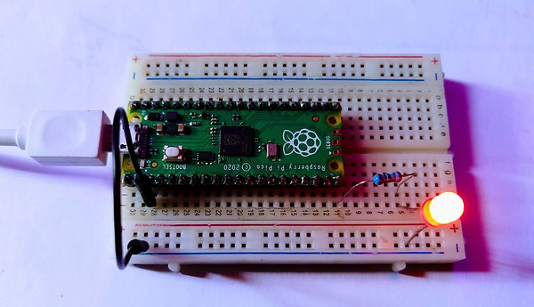
Fix your Raspberry Pi Pico board and LED on the breadboard.
-
Connect the shorter leg of your LED to any GND pin of the Pico.
-
Connect one end of your resistor to the anode leg of the LED, then the other end of the resistor to any digital pin (say GPIO15) of the Pico and the cathode leg of the LED to any GND pins of the Pico, as shown below:
.png)
Code
Below are sample codes to blink the external LED connected to our Pico using the picozero library.
Turn an LED on and off:
from picozero import LED
from time import sleep
led = LED(15)
led.on()
sleep(1) # pause for one second
led.off()
Toggle an LED to turn it on or off:
from picozero import LED
from time import sleep
led = LED(15)
while True:
led.toggle()
sleep(1) # pause for one second
Alternatively, you can use the blink() method:
from picozero import LED
led = LED(15)
led.blink() # on for 1 second then off for one second
Run the code, you should see the LED start to blink.
Digital Input Signal — Pushbutton
We saw above how we can send out a digital signal to control connected peripherals such as turning on and off an LED. Now, let's see how we can receive a digital signal from a push button.
Let's connect a push button to a Raspberry Pi Pico and detect when they are pressed.
Wiring
-
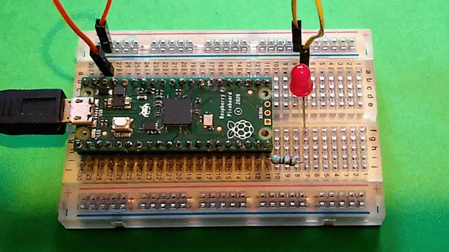
Adding to your previous LED circuit, Fix the push button across the center line on the breadboard.
-
Connect the button to the Pico with one leg to any digital pin (say Pin GP14) and the other to any GND Pin of the Pico, as shown below:
.png)
Code:
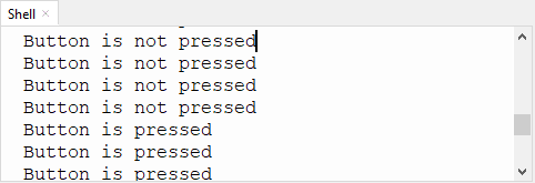
Create a new file in Thonny and add the code below:
from picozero import Button
from time import sleep
button = Button(14)
while True:
if button.is_pressed:
print("Button is pressed")
else:
print("Button is not pressed")
sleep(0.1)
Result:
Now, let's connect an LED to the Pico and then use the signals from the button to turn on and off the LED accordingly.
Circuit
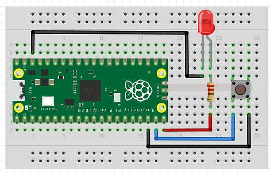
Add LED to your previous push button circuit.
-
Connect one end of your resistor to the anode leg of the LED, then the other end of the resistor to GPIO15 of the Pico, and the cathode leg of the LED to any GND pins of the Pico, as shown below:
.png)
Code
Create a new file in Thonny and add the code below:
from picozero import Button, LED
led = LED(15)
button = Button(14)
button.when_pressed = pico_led.on
button.when_released = pico_led.off
Run your code: When you press the button, the LED should come on and then go off when you release the button.
Alternative method:
from picozero import Button, LED
from time import sleep
led = LED(15)
button = Button(16)
while True:
if button.is_pressed:
led.on()
else:
led.off()
sleep(0.1)