
Analog Input and Output:
Potentiometer/PWM

Updated: Feb. 2025
Introduction
Analog signals are continuous signals that vary smoothly over time and can take on any value within a certain range. These signals represent physical quantities such as voltage, current, temperature, pressure, or sound waves in the real world.
Analog signals are used in various applications such as audio processing, telecommunications, instrumentation, and control systems. They are often converted into digital signals for processing by computers or digital devices, a process known as analog-to-digital conversion (ADC), but they remain prevalent in many aspects of technology and everyday life.
The Raspberry Pi Pico has four 12-bit ADC channels dedicated to analog input. One of these four pins is connected to the internal temperature sensor. The remaining ADCs are located at GPIO26, GPIO27, and GPIO28 as ADC0, ADC1 and ADC2,
respectively.
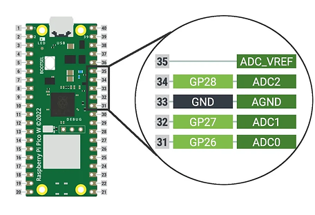
As mentioned earlier, the ADC channels are 12-bit, however, when we program the Pico with MicroPython, we get a 16-bit resolution. This is because, in the MicroPython ADC library, they have scaled the 12-bit resolution into a 16-bit resolution, which is why we will have a maximum ADC value of 65535 (i.e. 2^16) instead of 4096 (i.e. 2^12).
Potentiometers
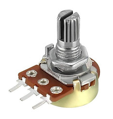
A potentiometer is a resistor that allows you to change the value of the resistance. They are often just called pots.
Turning the dial on the top of the potentiometer will change the resistance of the potentiometer, which the Raspberry Pi Pico can then read.
We'll be using a potentiometer to provide our analog input. First, let's assemble our hardware.
Hardware components
-
Raspberry Pi Pico
-
Breadboard
-
Potentiometer
-
Male-Male jumper wires
-
LED
Assemble Hardware
-
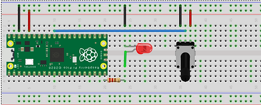
Fix your Pico to the breadboard.
-
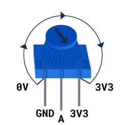
Fix the potentiometer also to the breadboard. Connect the center pin of the potentiometer to GPIO26 (ADC0) of the Pico, then one end of the potentiometer to any GND pin of the Pico, and the other pin a 3.3v pin of the Pico with jumper wires.
.png)
We'll read the potentiometer values first and display it on Thonny using MicroPython, with the few lines of code below:
from picozero import Pot # Pot is short for Potentiometer
from time import sleep
pot = Pot(26) # Connected to pin A0 (Pin_26)
while True:
print(f"Value: {pot.value}, Voltage: {pot.voltage}")
sleep(0.1) # slow down the output
The value and voltage should be 0 (or close to 0) when the potentiometer is turned all the way to the left. When it is turned all the way to the right, the value and voltage should be 1.0 and 3.3 respectively. If your values are the wrong way round you need to swap the jumper wires connected to GND and 3V3.
Analog Output (PWM)
Pulse Width Modulation, or PWM, is a technique for getting analog results with digital means. Digital control is used to create a square wave, a signal switched between on and off. This on-off pattern can simulate voltages in between the full Vcc of the board (e.g., 3.3 V on the Pico board) and off (0 Volts) by changing the portion of the time the signal spends on versus the time that the signal spends off. The duration of "on time" is called the pulse width. To get varying analog values, you change, or modulate, that pulse width. If you repeat this on-off pattern fast enough with an LED for example, the result is as if the signal is a steady voltage between 0 and Vcc controlling the brightness of the LED.
Let's now use these values from the potentiometer to control the duty cycle for PWM on the LED.
.png)
Use the code below:
from picozero import Pot, LED
# Potentiometer connected to GP26 (ADC0), GND and 3V
# LED connected to GP15
pot = Pot(26)
led = LED(15)
while True:
led.value = pot.value
Save and run the code. Tune the dial on the potentiometer to control the LED's brightness.