
Arduino Simulation using Proteus

Introduction
Testing out your project virtually: knowing what works and making the right adjustment before committing to the hardware is always a good idea. Although having your project work in a simulator like Proteus is not a guarantee that it will be perfect when you connect your hardware together, but it is always good to know what to expect from the simulator. In this tutorial we will learn how to simulate our projects using the Proteus circuit simulator software.
To have a clearer understanding of what we will be discussing in this tutorial, please check out our “Getting started with Proteus” tutorial if you haven’t already.
Getting started.
To be able to design our Arduino projects on Proteus, we have to download the various Arduino Libraries for Proteus and integrate them in your Proteus software.
There are various Arduino Libraries for Proteus out there you can download and integrate with Proteus. There are libraries ranging from Arduino boards, shields, and variety of sensors and display modules.
Download the Arduino UNO Proteus Library here.
After downloading from the link above, you should have a zipped file saved to you computer. Next, we have to extract the file and add it to our Proteus Library folder. To do this; copy the extracted files, go to your systems directory, on Windows should be SYSTEMS(C:) > ProgramData > Labcenter Electronics > Proteus 8 Professional > LIBRARY. Paste the copied files inside this folder and you are good to go. You can follow these steps for all other library installation.
Creating a new project on Proteus
Now you are done with the library installation let's open a new project on Proteus and start getting our hands dirty with Arduino circuit designs.
We shall assume at this point that you have installed the Proteus 8 software package.
To start the software, click on the Start (Windows) button and select Programs, Proteus 8 Professional and then click on the Proteus 8 application icon. Also, you can simply go to your desktop and double-click on the Proteus icon. The main application will then load and run and you will be presented with the Proteus home page, shown below:
Step 1
At the Proteus software home screen, click on the new project button. A "new project wizard" window should pop up.

Step 2
At the new project window, edit your project name and you can select the directory you new project will be saved, or you can just leave it to save at the "document" directory by default then click the "next" button to go to the next page.

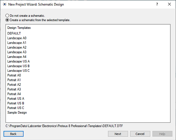
Step 3
On the new window, we need a schematic, which is already selected by default; as shown. So just click "next" to new page.
Step 4
On the new page, we do not need a PCB design "yet". So click on the "next" button to new page.

Step 5
Similarly, on the new page we will be writing our firmware (Arduino sketch) using the Arduino IDE and not the Proteus compiler. So check the "No firmware project" and click on the "next" button to new page.

Step 6
You should be on the final setup page. Just click on the "Finish" button
and a new Proteus Schematic window will pop open.

Designing a simple Arduino circuit.
Let's design a simple Arduino circuit to blink and LED. As we all know, blinking an LED is to a microcontroller what "Hello world" is to a new programming language.
While at our "Schematic capture window" on Proteus, go to the pick tool icon labelled "P", search for Arduino UNO on the search bar. Also, search for an LED (pick and LED labelled ACTIVE as shown to enable us see the blink effect). Then pick a resistor.
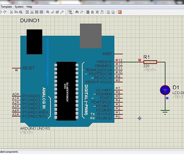
With your selected components, design a simple circuit as shown below. Connect the anode part of your LED through a 220 ohm resistor to pin 13 of the Arduino board, as shown below;
Writing and Loading the sketch to the Arduino.
We will blink our LED by just uploading the "Blink example sketch" from the Arduino IDE onto our virtual Arduino board in Proteus. Before we do that, there is a little tweak we need to do on the Arduino IDE.
Open your Arduino IDE, go to File > Preferences, a new window should pop up. Check the "upload" and "compile" boxes and the tweak is done.


Let's upload our blink example sketch. Click on File > Examples > Basics > Blink. A new
IDE window should pop up with the blink sketch.
.png)
On this new window, click on "verify"; your code should start compiling. When compiling is done, go to the "message window area" scroll through the messages displayed; look for a directory (one ending with .elf) as shown below.

Copy this directory to Proteus, double-click on the Arduino board; a window should pop up. You should see a bar labelled "Program file", replace any directory there (if any) with the directory you just copy (paste). This will tell Proteus to look for the source code to run the circuit at the the pasted directory.

This method is how you will be writing sketches using the Arduino IDE to run on Proteus.
Design your your sketch on Proteus, write sketch on the Arduino IDE, click on verify (not upload; as you only need upload while uploading code to physical Arduino board) to compile your code, then copy the directory and paste on the bar for program file on the Arduino board on Proteus, then you are good to go.
After you are done uploading the sketch to the Arduino, click on the "Run button" on Proteus; your LED should start turning ON and OFF with a one second intervals.
If that is the case; Congrats! you can now simulate your Arduino circuits on Proteus using the steps we have gone through.