
Proteus PCB Design and Circuit Simulator

Introduction
Simulation is the imitation of the operation of a real-world process or system over time. The act of simulating something first requires that a model be developed; this model represents the key characteristics or behaviors of the selected physical or abstract system or process. The model represents the system itself, whereas the simulation represents the operation of the system over time. (Wikipedia.)
Proteus VSM
PROTEUS VSM is a simulation software that allows professional engineers to run interactive simulations of real designs. With Proteus VSM it is possible to simulate complete microcontroller systems and thus to develop the software without access to the physical prototype. In the world were time to market is becoming more and more important, this is a real advantage.
Typically, engineers spend as much time finding and fixing problems and testing projects as they do in creating them in the first place. This is an area where Proteus VSM excels.
Proteus VSM will save time and effort during the design phase and in the testing/debugging phase. The ability to use the schematic in Proteus as a virtual prototype for firmware design and debugging improves the quality of the physical prototype. Less design iterations mean less delays at manufacturing and lower manufacturing costs.
Proteus is a paid application but you can download the free demo version from their official website https://www.labcenter.com/downloads. The demo version is fully functional except that it won’t allow you to save your designs.
Features of Proteus
Design
For embedded engineers, Proteus VSM bridges the gap in the design workflow between schematic capture and PCB layout. It enables you to write and apply your firmware to a microcontroller component on the schematic and then co-simulate the program within a mixed-mode SPICE circuit simulation. For design entry and development therefore you use the Proteus capture tool to draw a schematic representing the electronics for your project. Proteus capture is a long established product, combining ease of use with innovative features and powerful editing tools. It is used both to design ‘virtual hardware’ for Proteus VSM simulation and then also for PCB design using our PCB Layout module (ARES).
Simulate
Proteus can fully simulate the interaction between software running on a Microcontroller unit (MCU) and any analogue or digital electronics connected to it on the schematic. The MCU sits on the schematic along with the other elements of your design. It simulates the execution of your object code, just like a real chip. The models typically support all on-board peripherals of the real device. Unlike other simulators, the interaction of the MCU with the external circuit (schematic) is modelled down to waveform level and the entire system can therefore be tested.
Analyze
Proteus VSM includes a number of virtual instruments including an Oscilloscope, Logic Analyser, Function Generator, Pattern Generator, Counter Timer and Virtual Terminal as well as simple voltmeters and ammeters. In addition, we provide dedicated Master/Slave/Monitor mode protocol analysers for SPI and I2C - simply wire them onto the serial lines and monitor or interact with the data live during simulation. A truly invaluable (and inexpensive!) way to get your communication software right prior to hardware prototyping. Also available for more detailed analysis are graphing capabilities for things like frequency, fourier, distortion, noise or sweep analyses.
Debug
Whilst Proteus VSM is already unique in its capability to run near real time simulations of complete micro-controller systems, its real power comes from its ability to perform these simulations in single step mode. This works just like your favourite software debugger, except that as you single step the code, you can observe the effect on the entire design - including all the electronics external to the microcontroller. You have full access to variables display and watch window where you can monitor address and/or register contents. You can also set breakpoints on a logical condition of any watch window item making it easy for example to trap a timer overflow.
Getting Started on Schematic capture
Note: if you are using Proteus on your laptop it is advisable to use an external mouse. This will make it more convenient while navigating the software especially during zooming, panning, wiring, dragging and dropping of components etc.

Creating a new project
We shall assume at this point that you have installed the Proteus 8 software package.
To start the software, click on the Start (Windows) button and select Programs, Proteus 8 Professional and then click on the Proteus 8 application icon. Also, you can simply go to your desktop and double-click on the Proteus icon. The main application will then load and run and you will be presented with the Proteus home page, shown below:
Step 1
At the Proteus software home screen, click on the new project button. A "new project wizard" window should pop up.

Step 2
At the new project window, edit your project name and you can select the directory you new project will be saved, or you can just leave it to save at the "document" directory by default then click the "next" button to go to the next page.

Step 3
Edit your project name and add the ".pdsprj" extension (it will be added automatically anyway) then click on the "next" button. You can change were your project is saved by editing the "Path", or just leave it as default which is your documents folder: on Windows.
Step 4
On the new page, we do not need a PCB design "yet". So click on the "next" button to new page.

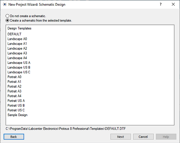
Step 5
Similarly, on the new page we will be writing our firmware (Arduino sketch) using the Arduino IDE and not the Proteus compiler. So check the "No firmware project" and click on the "next" button to new page.

We don't need a firmware project for now. We will discuss this when simulating our microcontroller with Proteus. (check out: 8051 simulation with Proteus). For now we just leave the box checked as shown above and click next.
Step 6
You should be on the final setup page. Just click on the "Finish" button and a new Proteus Schematic window will pop open.

-
Click on the "Finish" button and you will be greeted with a new schematic capture window for you to get started with your circuit design. As shown below;

Schematic capture window
Opening an existing project
To open an existing project in Proteus, open your Proteus software and while at the home page click on that will pop-up your window explorer; navigate to were your project is saved, click on the project you wish to open and click ‘open’ it will automatically open your project in Proteus.
Selecting Parts from the Library
Before carrying out your schematic design, you need to pick the electronic components needed for your design from the library. To do this the following steps are to be taken:
You can select parts from the library in one of two ways:
-
Right click the mouse on an empty area of the schematic and select Place – Component - From Libraries from the resulting context menu.
-
Secondly, click on the P button at the top left of the Object Selector as shown below. You can also use the Browse Library icon on the keyboard shortcut for this command (by default this is the P key on the keyboard), as shown below:

-
Type the component name you wish to pick in the ‘keywords bar’ which in this case is ‘led’. You can even select their ‘category’, ‘manufacture’ etc. to make thing easier.

-
Select from the numerous options the one you need, double click on it and it will be added to your component list as labeled 4 in the diagram above, start again from step2 till you get all your components then click OK.
Either of these two methods will cause the Device Library Browser dialogue form to appear. For reference, the following is a list of all the components we will need for our design:
If you know the part (component) you wish to import from the library, try entering it into the keyword dialogue form. This gives a direct result and we can then simply double click on the results list to add it to Object Selector section.
In the case that we don’t know the exact name of the part we wish to import, Proteus makes it possible for you to type in descriptive keywords and then browse the results to find a specific part: so instead of typing in ‘CHIPRES1K’, you can just type in ‘1K resistor’ in the keywords dialogue box and search through your result to locate your desired component.
If there is a part you need for your project which is not included in the installed libraries, you can quickly download and import the parts free of charge from popular third-party vendor such as Ultra-Librarian, SnapEDA, Library Loader or PCB Library Expert.
You can customize the information displayed in the Library Browser’s results list by right clicking the mouse on the results list. The context menu provides you with options to display Categories, Sub-Categories, Manufacturer and Library alongside each result.
Terminals
We use terminals in schematic design simply to terminate a wire and assign a connection. Often this connection is to either power or ground but it can just as easily be to another wire elsewhere on the circuit. Terminals allow us both to vastly reduce actual wiring (avoiding spaghetti schematics) and to make connections between different sheets on the schematic. To place terminals, start by selecting the terminal mode; this will switch the Object Selector and provide us with a listing of the available terminal types. As shown below:

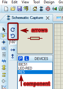
Rotating a part
You can also rotate parts 'live' when in placement mode. Left click the mouse once to enter placement mode (at this point you will see the component outline following the mouse) and then use the '+' and '-' keys on the numeric keypad to rotate the component as you are placing it. Left click again to commit the placement in the normal way.
Placing Objects on the Schematic
Having selected the parts we need the next thing is to actually place them on the drawing area – the Editing Window – and wire them together.
-
Select the device from the Object Selector.
-
Left click on the schematic to enter placement mode.
-
Move the mouse to the desired location for the part, then left click the mouse again to ‘drop’ the part and commit placement.
Wiring Up
Having placed all the requisite components we now need to wire them together. Proteus makes it easy to wire a circuit as simple and quick as possible:
Follow-Me Wire Autorouting
After starting to place a wire, the proposed route of the wire will follow the movement of the mouse orthogonally to the termination point of the wire.
Live Cursor Display
The cursor will change as a visual indicator when wiring to show when a wire can be placed, when a wire can be terminated and when a wire is being placed.
The basic procedure for placing a wire between two pins is given below, using the connection between the 10K resistor pin and the LED as an example:

-
Move the mouse over device pin - the cursor will change to a green pen.
-
Left click the mouse and then move it until it is over the pin of the other device you wish to connect to. The wire will follow the mouse and the cursor / pen is white during wiring.
-
Left click the mouse again to commit the connection and place the wire.
The procedure for wiring onto an existing wire is almost identical but there are a couple of items to note:
-
You cannot directly start a connection from an arbitrary point on a wire; If, during a design, you want to make a wire-to-wire connection you must first place a junction dot on the wire and then wire from the junction dot to the other wire. If you want to adjust a wire after placement then simply right click on the segment you want to move and then either select the ‘Drag Wire’ context menu option or simply depress the left mouse button and drag to the new location.
-
When you terminate the connection on another wire a junction dot will be placed automatically to complete the connection.
Editing component property
To change the property of any component, for example ‘resistor’, right click on the component and pick any of the options from the pop-up window. Let’s say you wish to change the resistance of a resistor, just right click on the resistor, select ‘Edit Properties’ and the ‘Edit component’ window’ will pop-up, edit the resistance value in the highlighted box, then click ‘ok’.


Running your simulation
After compiling and your source code is error free, go to your ‘schematic capture interface’, on the bottom left corner, click 'button 1' to start your simulation, 'button 2' and '3' to 'pause' and 'access' the debug interface and 'button 4' to 'stop' simulation as shown below.

Adding text to your design
If you wish to add text such as your name in your design. Simply go to the tool bar on the left-hand side of your screen, left-click on the 2D Graphics Text Mode (denoted with the A symbol), select the 2D GRAPHIC option from the menu as shown below. Left-click on your design area and a window will pop-up; type your text on the box labeled string. You can also edit your text like; bold, change size, italicize etc. with the numerous options available, click the ‘ok’ button then place the text where you wish to just as other components.


Moving block circuitry
Often we need to move parts or blocks of circuitry after placement and now is a good time to cover the different ways in which we can do that. The procedure for this should be familiar to most users; we need to select the object(s) we want to move, left depress the mouse, drag to the new location and finally release the mouse to drop.
We can select an object in several ways as detailed below:
-
Choose the Selection Icon and then left click on the object. This is a standard technique found in most graphical applications and will tag any object. Bear in mind when using this technique that you must change back to component mode for example, when you wish to perform other actions such as placing components etc.
-
Right clicking the mouse on an object will both tag the object and present a context menu containing available actions on that object.
-
Draw a tagbox around the object by depressing the left mouse button and dragging the mouse to form a box encompassing the object to be selected. This method will work for any object (or indeed sets of objects). Sizing handles are provided to allow you to resize the tagbox in the event that it does not fully enclose the object. This is the technique that should be used for moving multiple, connected objects or blocks of circuitry.
Zooming
There are several ways to zoom in and out of areas of the schematic:
-
Point the mouse where you want to zoom in and out of and roll the middle mouse button (roll forwards to zoom in and backwards to zoom out).
-
Point the mouse where you want to zoom in or out of and press the F6 or F7 keys respectively.
-
Hold the SHIFT key down and drag out a box with the left mouse button around the area you want to zoom in to. We call this Shift Zoom
-
Use the Zoom In, Zoom Out, Zoom All or Zoom Area icons on the toolbar.
Zoom Icons
Panning
As with zooming, there are a number of options for panning across the editing window.
-
Click on the middle mouse button to enter track pan mode. This puts the schematic in a mode where the entire sheet is picked up and will move as you move the mouse. The track pan cursor will indicate when you have entered this mode. Left click the mouse again to exit track pan mode.
-
To simply 'pan' the Editing Window up, down, left or right, position the mouse pointer over the desired part of the Editing Window and press the F5 key.
-
Hold the SHIFT key down and bump the mouse against the edges of the Editing Window to pan up, down, left or right. We call this Shift Pan.
-
Should you want to move the Editing Window to a completely different part of the drawing, the quickest method is to simply point at the center of the new area on the Overview Window and click left.
-
Use the Pan Icon on the toolbar
Note that when using the track pan method above you can also zoom in and out by rolling the mouse wheel. So, click the middle mouse button to pick up the sheet and move the sheet by moving the mouse and zoom the sheet by rolling the middle mouse button. Left click to 'drop' the sheet and exit track pan mode.
It is well worth spending a few moments familiarizing yourself with navigation in Proteus - it is after all one of the most common operations you will perform. In particular, learning to use the middle mouse button both for track pan and for zooming will save you time during schematic design.
Printing
To print the schematic, first select the correct device to print to using the "Printer Design" command on the "File menu". This activates the Windows common dialogue for printer device selection and configuration. The details are thus dependent on your particular version of Windows and your printer driver - consult Windows and printer driver documentation for details. When you have selected the correct printer, close the dialogue form and select the Print option on the File menu to print your design. For our purposes we will simply center the schematic output on the page and print. Do this now by right clicking on the Print Preview and selecting the Position Output at Center option as shown below.
You can also export the schematic directly in PDF format from the Output Menu

If you followed the course till this point. HEY.....! you did it.

You can now start Designing and Simulating your basic electronic circuits.
Keep following our Tutorials to advance your skills.