
Interfacing Analog Peripherals to Pi via External ADC
Introduction
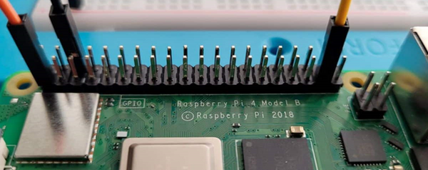
Unlike some microcontrollers (e.g., Arduino), the Raspberry Pi does not have built-in analog-to-digital (ADC) or digital-to-analog (DAC) converters. This means that the Raspberry Pi cannot natively read analog signals directly from sensors like temperature or gas sensors, nor can it output true analog signals.
A. Reading Analog Signals: External ADC:
To read analog signals, you need an external ADC chip, such as the ADS1015/ADS1115. The ADS1x15 can be connected to the Raspberry Pi via the I2C interface, allowing the Pi to read analog signals from sensors.
The ADS1115 breakout board is a high-resolution analog-to-digital converter (ADC) that can be used in conjunction with single-board computers such as the Raspberry Pi.
By incorporating the ADS1115 module, which boasts a 16-bit ADC resolution, the Raspberry Pi’s ability to handle analog inputs can be vastly expanded. With the ADS1115, the smallest voltage that can be measured is 5V / 65536 = 0.000076V (76uV), offering enhanced precision for your projects.
ADS1115/1015 External ADC
The ADS1115 (16-bit) and ADS1015 (12-bit) 4-channel breakout boards are perfect for adding high-resolution analog-to-digital conversion to any microprocessor-based project. These boards can run with power and logic signals between 2V to 5V, so they can be compatible with all common 3.3v and 5v processors. As many as four boards can be controlled from the same 2-wire I2C bus, giving you up to 16 single-ended or 8 differential channels.
These two boards are very similar, meaning they are connected the same way and even function with the same library. They differ only in resolution and speed. The ADS1115 has a higher resolution and the ADS1015 has a higher sample rate.
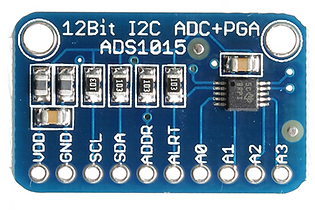
ADS1015 ADC
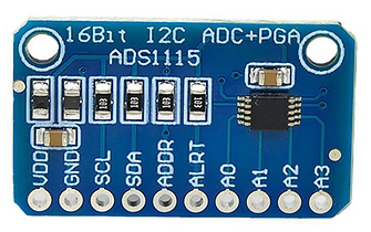
ADS1115 ADC
You can also make use of this two-in-one ADS1015/ADS1115 module then edit your code to select which resolution you wish to make use of.
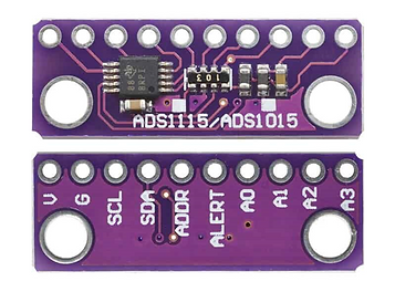
ADS1015/1115
Interfacing ADS1115 Module with Raspberry Pi
Interfacing an ADS1115 module with a Raspberry Pi 5 is straightforward, as both devices use the I2C communication protocol. Follow the circuit below to make your circuit connections.
Components:
-
Raspberry Pi
-
ADS1115
-
Breadboard
-
Male – Female jumper wires (4)
-
Male – Male jumper wires (5)
-
Potentiometer (analog sensor)
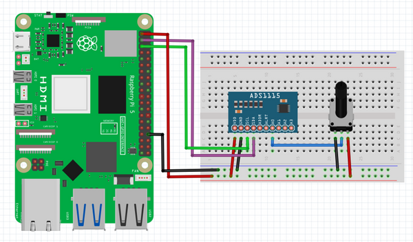
Raspberry Pi with Potentiometer
ADS1115 Python Library Installation
Before moving to the Python programming part, we need to install ADS1115 Library on Raspberry Pi.
Open a terminal window on your Raspberry Pi. Run the following command to install the ADS1x15 Python library.
sudo pip3 install adafruit-circuitpython-ads1x15
Below is a Python Code to interface ADS1115 16-bit ADC Module with Raspberry Pi. The code will read analog values from Pin A0 fed using the potentiometer.
Python code: ADS1115.py
import board
import busio
import adafruit_ads1x15.ads1115 as ADS
from adafruit_ads1x15.analog_in import AnalogIn
import time
i2c = busio.I2C(board.SCL, board.SDA) # Initialize the I2C interface
ads = ADS.ADS1115(i2c) # Create an ADS1115 object
# Define the analog input channels
channel0 = AnalogIn(ads, ADS.P0)
channel1 = AnalogIn(ads, ADS.P1)
channel2 = AnalogIn(ads, ADS.P2)
channel3 = AnalogIn(ads, ADS.P3)
# Loop to read the analog inputs continuously
while True:
print("Analog Value0: ", channel0.value, "Voltage0: ", channel0.voltage)
print("Analog Value1: ", channel1.value, "Voltage1: ", channel1.voltage)
print("Analog Value2: ", channel2.value, "Voltage2: ", channel2.voltage)
print("Analog Value3: ", channel3.value, "Voltage3: ", channel3.voltage)
time.sleep(1) # Delay for 1 second
B. Analog Output (PWM) on Raspberry Pi:
PWM (Pulse Width Modulation): While the Raspberry Pi doesn't have a true DAC for analog output, it can simulate analog signals using PWM. PWM rapidly switches a GPIO pin between HIGH and LOW states, and by varying the duty cycle (the ratio of time the signal is HIGH vs. LOW), you can simulate a varying voltage.
To generate PWM (Pulse Width Modulation) output on the Raspberry Pi 5 using the GPIO Zero library, you can control devices like LEDs, motors, or servos by varying the duty cycle of the signal.
Here’s how you can create a simple PWM control to adjust the brightness of an LED:
Python code
from gpiozero import PWMLED
from time import sleep
# Define the GPIO pin number where the LED is connected (e.g., GPIO 18)
led = PWMLED(18)
# Increase and decrease brightness
while True:
for brightness in range(0, 101):
#Brightness value must be between 0 (off) and 1 (full brightness)
led.value = brightness / 100
sleep(0.01)
for brightness in range(100, -1, -1):
led.value = brightness / 100
sleep(0.01)