
Interfacing Digital Peripherals to Pi via GPIO
Introduction
As we saw earlier, the I/O in GPIO stands for Input and Output, respectively, meaning that for every component connected to the Pi, you either read signals from it (Input) or send signals to it (Output).
On a broader scale, the signals involved in these I/O operations can be classified into two categories: Digital and Analog signals.
A. Digital Input Operations on Raspberry Pi
Reading Digital Signals: You can configure a GPIO pin as an input to read digital signals. For example, you can connect a push button to a GPIO pin, and the Raspberry Pi can detect when the button is pressed (HIGH) or not pressed (LOW).
Component list:
-
Raspberry Pi 4 or 5
-
Breadboard
-
Push button
-
Jumper wires (2 Male – Female and 1 Male – Male)
Connect the circuit as shown below:
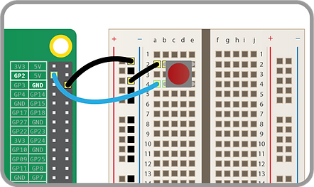
Raspberry Pi with Push button
Python code: button.py
from gpiozero import Button
button = Button(2)
button.wait_for_press()
print('You pushed me')
Digital Output Operations on Raspberry Pi
Controlling Digital Devices: You can set a GPIO pin as an output to control digital devices like LEDs, relays, or buzzers. The Raspberry Pi can switch the pin state to HIGH (3.3V) or LOW (0V) to turn the device on or off.
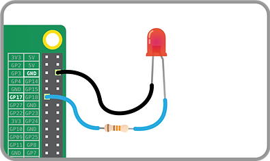
Raspberry Pi with LED
Python code: led.py
from gpiozero import LED
led = LED(17)
while True:
led.on() #This command will keep your LED on
led.off() #This command will keep your LED off
To blink your LED, you can add the sleep() function to turn on the LED, pause for some time, then turn it off. Having this inside a loop will keep your LED blinking.
Python code: blink_led.py
from gpiozero import LED
from time import sleep
led = LED(17)
while True:
led.on() #LED on
sleep(1) #pause for 1 second
led.off() #LED off
sleep(1) #pause for 1 second